Data acquisition |
|
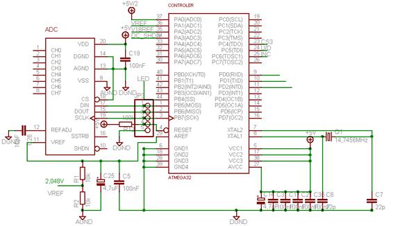
Table of contents This feature was one of the first parts we designed. It makes easier the dimensioning of the others components. The microcontroller ATMEGA32 is sufficient for our application. It includes height 10-bits ADC that is not sufficient to measure the angular rate, the magnetic field or the acceleration but enough to control the temperature or the voltage. Therefore we decided to use serial ADC 12-bits (MAX186AEPA). After a calculation of the sensors resolution, it shows that 12 bits is enough. With a 14-bit application, we will not obtain a better signal than the actual ADC; we just collect a more great quantity of noise. On the Max186, 1LSB = 4,096/212 = 1mV On the Atmega32, 1LSB = 4mV The input signal on the ADC is comprised just between 0 and 4,096V. Consequently, all the signals have to be centred on 2,048 V. The eight input channels of the ADC are divided as follow: -2 channels for the accelerometer (one for each axis) -3 channels for the magneto-sensors (one for each axis) -1 channel for the gyro. We have still two channels free. They will be used to supervise the reference voltage and the inner temperature of the sensor. Note: A problem with the microcontroller is that it is not design to operate outdoors (it doesn’t work when the temperature below 0°C).
|